
ENGINES
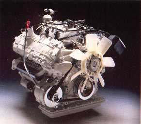
V-6 engine B280 E & F delivered in the 780 here shown without powersteering.
Better leichtmetal V6: now 14 hp more.
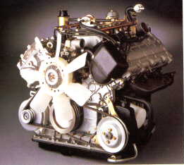
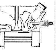
V-6 engine B280 E & F delivered in the 780 with powersteering.
Miraceles V6
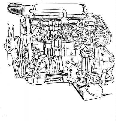
Diesel Engines
The difference between petrol and diesel lies in the combustion and its control. A petrol engine operates with a generally
constant mixture of air and fuel, and the output is regulated by volume of the mixture. The diesel engine operates
with a consistent air surplus. The air volume is constant and the output is regulated by the amount of fuel supplied.
In a petrol engine the fuel mixture is ignited by an electric spark. In a diesel engine ignition is accomplished by
compression heat.
These differences in principles make fuel systems and combustion chambers differ, whilst for example the engine blocks,
cooling systems, lubricating systems, valve systems, etc. remain pretty well alike.
Diesel principle
The diesel engine is a piston engine in wich the pistons inducts and compresses the air. The compression must raise the
temperature of the air so much that it can ignite the fuel. As diesel oil is less inflammable than petrol the diesel engine
must operate with relatively high compression ratios. The lower limit is about 12:1, but the most usual ratios are 18-22:1.
The powerfull compression raises the air temperature to about 650-750°C. At the end of the compression cycle atomized fuel
is injected and ignited by the hot air. The engine speed and output are regulated by the injection of greater or smaller
quantities of fuel, whilst the air volume constantly remains at maximum. The continuous air surplus provides extremely good
combustion and low values with regard to nitric oxide (NOX), carbon monoxide (CO) and hydrocarbons (HC) in the exhaust gases.
CHARACTERISTICS
Three factors that are build into the basic principles of the diesel engine also provide the engine with its typical
characteristics.
1. High pressure
The high compression ratio means that the engine must always be made more strongly than the petrol engine.
But the high compression ratio also provides a better utilization of the fuel.
Consequently a diesel engine is very efficient.
2. Air surplus
The continual air surplus means that all the fuel can be consumed.
consequently, if porperly set, a diesel engine provides excellent combustion.
3. Limited revolution range
The mixture of the air and fuel takes places in the combustionchamber. This process requires a certain amount of time.
If revolutions are too high the air and fuel do not get time to mix properly, which means that combustion will be not be
absolute. Thus diesel engines have a lower maximum engine speed than petrol engines.
Different types of combustion chambers
Diesel engines have either direct or indirect fuel injection.
1. Direct injection
means that the fuel is injected in a ombustion chamber immediately above or in the piston.
The injector is furnished with a number of very fine holes through which the fuel is distrubuted in all directions and
mixture with the air is accomplished by the turbulance which arises when the piston rises.
2. Indirect injection
means that the fuel is injected in a separate chamber. Here, one must differentiate between two types.
In an antechamber diesel the entechamber composes about 25% of the total combustion area.
The fuel is distrubuted in the antechamber and ignites. However, combustion mainly takes place in the combustion chamber
above the piston.
In a swirl-chamber diesel the swirl chamber composes about 50% of the combustion area. A powerful turbulence takes place in
the swirl chamber that effectively mixes the air and fuel. In this case a greater part of the combustion takes place in the
swirl chamber than in an antechamber diesel. In the indirect injection diesel the combustion chamber has a relatively large
area. This provides heat losses that sometimes mean that with a cold engine the ignition temperature cannot always be reached.
Therefore engines with indirect injection are equipped with a glow plug located in the outer chamber. Prior to starting,
the glow plug is heated electrically until it is sufficiently hot to ignite the fuel.
Both direct and indirect injection have advantages and disadvantages. The advantages of the direct injection diesel are
primarily that the combustion chamber has a small area, resulting in small heat losses, and that the whole of the combustion
takes place directly above the piston, providing small pressure losses.
Due to the more effective mixture of the fuel and air, the indirect injection diesel engine can be equipped with a more
simple injector, which is less sensitive. The powerfull turbulence provides a more effective air/fuel mixture within much
shorter periods. Therefore a diesel engine with indirect injection can be made to run at higher speeds than the direct
injection type. The upper revolution limit for a direct injection diesel engine is about 50r/s (3000 r.p.m.).
Injection equipment
The efficiency of a diesel engine is greatly dependent on the injection equipment. Effective combustion requires that fuel is
injected in the right quantities, at the right time and that it is so atomized that the induction air is effectively utilized.
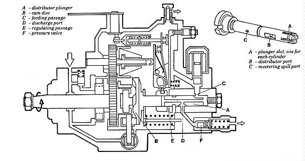
Fuel injection pump
The fuel injection pump is the unit in the fuel system that regulates the amount of fuel injected and point of time for
injection. In other words the fuel injection pump determines the engine speed and output. Generally speaking there are two
types of fuel injection pump. To a great extent, small engines are equipped with rotor pumps, in which one plunger carries
out all the pumping work for all the cylinders. A special fuel distribution unit ensures that the fuel is directed to the
same unit acts as both pump plunger and distributor. Others have a number of plungers that operate simulateneously with the
same volume of fuel. The capacity of the rotor pump is rather small and consequently in-line pumps are used on larger
engines, in which there is one pump cylinder for each engine cilinder.
Distributor pump
The distrubutor pump described here is of the sort used for e.g. the Volvo D24 engine.
The pump, briefly, consists of two main systems: one fuel-feed pump that draws fuel from the tank and one high-pressure
distributor pump that distributes the fuel to the cylinders.
The drive shaft of the pump operates the feeding pump as well as the cam disc and distributorplunger.
The cam disc has one disc for each cylinder giving the and plunger a rotating and a pulsating movement.
When cam disc and plunger is in its lowest position, one plunger slot is facing the feeding passage and fuel is entering
the plunger. The cam disc and plunger continues to rotate, which closes the feeding passage. The forward movement of the
plunger will put the fuel under high pressure. When the distributor port of the plunger faces the discharge port,
the high pressure fuel will open the pressure valve and via the injector be injected into the swirl chamber. The injection
is interrupted when the meetering spill port of the plunger faces the regulating passage, thus lowering the fuel pressure
under the opening limit of the pressure valve.
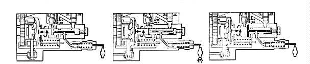
Rotor pump
 The fuel is conveyed in the conventional manner from the tank with the aid of a fuel feed pump. The fuel then continues
to a transfer pump, which is built into the rotor pump. Here the fuel pressure is increased to a value that stands in
relation to the engine speed-the transfer pressure. This relationship is kept constant with the aid of a valve.
The fuel then passes through a metering valve that decides how much fuel is to be injected. The metering valve is
controlled by the accelerator pedal in combination with a centrifugal regulator.
The regulator function is described later on.
The pump rotor with its two plungers, has two different functions: to increase the fuel pressure to the injection pressure,
and to distribute the fuel to the right cylinder at the right instant.
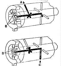
The rotor has a duct system connected up to openings in the rotor surface . In certain posistions these openings are
opposite the corresponding openings in the distributor housing. When this takes place, at "A" in the illustration, fuel is
transferred from the metering valve to the rotor. The fuel fills the duct system and forces out the plungers, "B".
The outer ends of the plunger rest on a cam ring via rollers, When the rotor continues its turn the inlet opening closes,
whereupon the cams on the ring press the plungers inwards. The fuel now increasees to injection pressure.
In the next position the outlet opening, "C", passes the line to one of the injectors, and the fuel delivered to this
injector under high pressure. The point of time for injection can be varied due to the fact that the whole of the cam
ring can be turned. Inside the pump there is an intentional leakage of fuel which passes betweeen all moving parts and
then returns to the fuel filter.
This fuel acts as a lubricant.
The fuel is conveyed in the conventional manner from the tank with the aid of a fuel feed pump. The fuel then continues
to a transfer pump, which is built into the rotor pump. Here the fuel pressure is increased to a value that stands in
relation to the engine speed-the transfer pressure. This relationship is kept constant with the aid of a valve.
The fuel then passes through a metering valve that decides how much fuel is to be injected. The metering valve is
controlled by the accelerator pedal in combination with a centrifugal regulator.
The regulator function is described later on.
The pump rotor with its two plungers, has two different functions: to increase the fuel pressure to the injection pressure,
and to distribute the fuel to the right cylinder at the right instant.
The rotor has a duct system connected up to openings in the rotor surface . In certain posistions these openings are
opposite the corresponding openings in the distributor housing. When this takes place, at "A" in the illustration, fuel is
transferred from the metering valve to the rotor. The fuel fills the duct system and forces out the plungers, "B".
The outer ends of the plunger rest on a cam ring via rollers, When the rotor continues its turn the inlet opening closes,
whereupon the cams on the ring press the plungers inwards. The fuel now increasees to injection pressure.
In the next position the outlet opening, "C", passes the line to one of the injectors, and the fuel delivered to this
injector under high pressure. The point of time for injection can be varied due to the fact that the whole of the cam
ring can be turned. Inside the pump there is an intentional leakage of fuel which passes betweeen all moving parts and
then returns to the fuel filter.
This fuel acts as a lubricant.
In-line pump
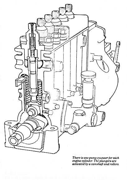 For each engine cylinder there is a pump unit composed of one plunger in each barrel.
The plunger is so precise that no separate seal is required. The plunger movement is governed by a camshaft, With the use
of different types of pistons and cam shapes one can accomplish differing injection characteristics.
Fuel enters and leaves the barrel through holes in the barrel wall. When the plunger is in its lower posistion fuel flows
into the space above the plunger. When the plunger then moves upwards it closes the inlet opening and the pressure of the
fuel above the plunger increase until it so high that it can open the needle valve in the injector, to where the pressure
is transferred through a fuel line. When the plunger approaches its uppermost position, the opening in the cylinder wall
opens again, but now below the plunger. The residual fuel above the plunger and out through the opening. At this instant
the fuel pressure falls quickly, and the needle valve in the injector closes. The stroke of the plunger cannot be varied
due to the fact that the plunger is furnished with an oblique edge. The posistion in which the plunger begins to open in
the cylinder wall can be changed by twisting the whole of the plunger. Usually, plungers have flat tops and oblique bottoms.
Injection than always commences at the same camshaft posistion and continues for a longer or shorter time dependent on the
angle of the plunger.
There are also models in which the plunger has an oblique top, which means that the point of time for the commencement of
injection can be changed by twisting the plunger. All of the plungers are twisted simultaneously, for the whole of the pump,
by a common control rod.
For each engine cylinder there is a pump unit composed of one plunger in each barrel.
The plunger is so precise that no separate seal is required. The plunger movement is governed by a camshaft, With the use
of different types of pistons and cam shapes one can accomplish differing injection characteristics.
Fuel enters and leaves the barrel through holes in the barrel wall. When the plunger is in its lower posistion fuel flows
into the space above the plunger. When the plunger then moves upwards it closes the inlet opening and the pressure of the
fuel above the plunger increase until it so high that it can open the needle valve in the injector, to where the pressure
is transferred through a fuel line. When the plunger approaches its uppermost position, the opening in the cylinder wall
opens again, but now below the plunger. The residual fuel above the plunger and out through the opening. At this instant
the fuel pressure falls quickly, and the needle valve in the injector closes. The stroke of the plunger cannot be varied
due to the fact that the plunger is furnished with an oblique edge. The posistion in which the plunger begins to open in
the cylinder wall can be changed by twisting the whole of the plunger. Usually, plungers have flat tops and oblique bottoms.
Injection than always commences at the same camshaft posistion and continues for a longer or shorter time dependent on the
angle of the plunger.
There are also models in which the plunger has an oblique top, which means that the point of time for the commencement of
injection can be changed by twisting the plunger. All of the plungers are twisted simultaneously, for the whole of the pump,
by a common control rod.
High-pressure lines and injectors
In the resting postion, the injector openings are blocked. The passage opens when the fuel pressure is high enough to
overcome a given spring pressure, and closes when the fuel pressure falls to a pressure which is about 75% of the opening
pressure. The fact that the closing pressure is lower depends on the fuel pressure working on a larger area when the needle
valve is open. The injector has a return line that returns the insignificant leakage that passes the valve.
This prevents the information of an inhibitive counter-pressure on the rear of the plunger.
The high-pressure pipe between the pump and the injector must have a volume as small as possible and the walls must also
be as stiff as possible to prevent the system from becoming too elastic. Elasticity reduces the precision of the injection
cycle. The inner diameter of the line must be precisely adapted to each type of engine.
Regulator
If the engine is not to stall or run at an excessively high speed when the load is changed the fuel supply must be governed
by a regulator. The regulator registers the engine speed and automatically influences the fuel pump when the engine speed
is changed. There are three different regulation characteristics:
1.
|
The regulator that keeps the engine at one constant speed, as used on generators, pneumatic pump, etc. |
2.
|
Regulators that govern max. and min. revolutions. Influance idling and max. speeds.
The areas in between are directly influenced by the accelator pedal. |
3.
|
All speed regulators. Keep the speed constant at a level set by the accelerator pedal.
Consequently one does not need to increase acceleration when running up inclines, etc. |
The section of the regulator that regulates the engine speed consisits of a pair of spring-loaded centrifugal weights.
The greater the speed, the further the weights are forced out by the centrifugal force. The posistion of the weights
influences the fuel pump control rod, which regulates the amount of fuel.
text en picture's from Volvo-Press kit 1981.
Go To Top of Page